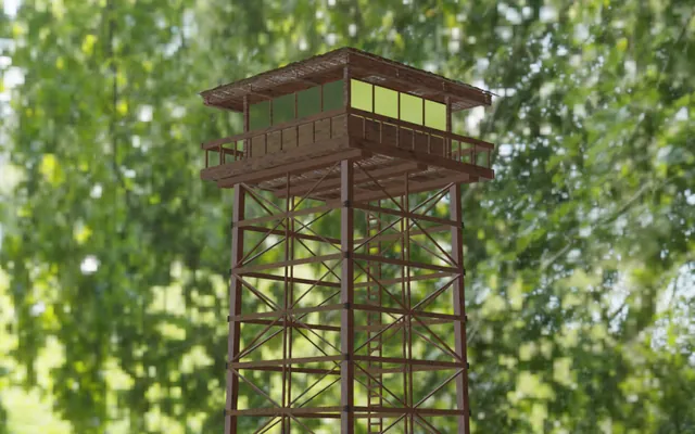
One generator instead of ten review rounds: a procedural lookout tower in Blender Geometry Nodes

Adriano Muricy · Technical Artist
Made for Eggplant VFX (Toronto), Urban Legends, episode "Scuba Diver"

Default output of the generator

The problem

The episode needed a few versions of an old wooden fire-lookout tower. What the director hadn't settled was the design itself: how tall, how many sections, how thick the beams, how big the cabin, how many windows. Those choices depended on how each camera angle read, and the camera angles were still changing.

The usual approach is to model one tower, send it, get notes ("two sections shorter", "chunkier legs on the low angle"), rebuild it and repeat. Every round costs modelling time. Worse, the notes can conflict from shot to shot.

So I didn't send a tower. I sent a tower generator: two Geometry Nodes modifiers with exposed parameters, so the team could dial in a structure per shot and lock it when the framing was approved.

A note on the materials. They are deliberately simple. Most of these towers were never meant to be final pixels. They gave a correct 3D perspective reference that a DMP artist would paint over, or that a texture/sculpt artist would push further once the hero design was picked. The shading only needed to read as weathered wood and concrete, and it needed to behave when the geometry changed. More on that below.

Four towers from the same file, only modifier values changed
The same two node trees with different modifier values. EEVEE re-renders from the generator file.

Scene layout

The asset is split across two generator objects plus a few helper objects:

Object Modifier stack Role
Tower Base Gen GN - Beam Gen 2 → Lattice Legs, cross-bracing, horizontal rings, concrete feet, stacking
Cabin Gen GN - Top Cabin → Auto Smooth Floor, joists, railing, cabin walls, glass, shingled roof, ladder hatch
Lattice (2×2×2) used by the tower and the ladder Flares the base: the bottom ring of points is scaled ×1.47
Empty + 3 ladder meshes ladder rails and rungs (Array) The Empty also drives the hatch cut in the cabin floor
bracket 1 / bracket 1.001 hidden Source meshes for the metal brackets, pulled in with Object Info

Exposed controls on Tower Base Gen: GRID SIZE, GRID HEIGHT, Amount (sections, 1–8), Inner Beam Section (cm), Horizontal Beam Thick (cm), Horizontal Beam Height (cm), THICC UPBEAM Thickness, Cement Base Width / Height / Top Size, Upright Beam Height.

Exposed controls on Cabin Gen: Floor Size, Floor Plank Width (cm), Floor Plank Depth (cm), MidBeam Thickness (cm), Roof Drop (Desceção do Teto), Cabin Roof Height (Altura Teto Cabine), Inner Cabin Scale, and Value (railing density).

Every "(cm)" input is multiplied by 0.01 inside the tree. The people using the tool could think in lumber dimensions while the scene stayed in metres.


Part 1: Tower Base Gen

Frame-level flow of GN - Beam Gen 2

The tree has 189 nodes organized in labeled frames. Almost everything is built from one idea, repeated:

Make a tiny 2×2 grid, turn its edges into a curve, and sweep another curve with it.

A 2×2 Mesh Grid has four vertices and four edges: a square. Run it through Mesh to Curve and Set Spline Cyclic and you get a closed rectangular profile. Feed that profile into Curve to Mesh (Fill Caps on) with any path, and you get a capped timber beam of exactly the section you asked for. Beam dimensions are just the grid's Size X / Size Y.

MAIN GRID: where the uprights go

Two 2×2 grids define all the placement:

No hard-coded positions. When the footprint changes, both point sets follow.

UPRIGHT BEAMS: lines on points, then lathe

X FRAME: cross-bracing from four vertices

This is my favourite trick in the file. The X bracing on every face comes from a single 2×2 grid:

  1. Grid of GRID SIZE, scaled to 0.99 so the braces sit just inside the legs.
  2. Index % 1.5 splits the four vertices into two diagonal pairs. A Boolean NOT gives the other pair.
  3. Two Set Position nodes raise each pair by GRID HEIGHT (the offset comes from the SECTION HEIGHT frame).
  4. Both results are joined. In each copy, every edge of the square now runs from a low vertex to a high vertex, so every edge is a diagonal. The two copies lean opposite ways and cross into an X on every face.
  5. Mesh to Curve → sweep with the inner-beam profile. The Factor is captured into beams_vec_2.

That's four vertices and a modulo in place of a bracing system that would otherwise need its own math per face.

HORIZONTAL BEAMS: rings, IDs and brackets

BASE ELEMENTS: feet that know where the stack starts

MANUAL DUPLICATES: stacking sections

A section is X frame + uprights + horizontal rings, joined. The Manual Duplicates group then builds the tower height:

The result is 1 to 8 stacked sections from one integer. It's the most brute-force part of the file, and I come back to it in the last section.

Lattice: the flare

The raw generator output is a straight prism. A 2×2×2 Lattice modifier with the bottom ring of points pushed out (×1.47) gives the splayed-leg silhouette of a real fire lookout. The ladder meshes use the same lattice so they follow the lean.


Part 2: Cabin Gen

Frame-level flow of GN - Top Cabin

The cabin tree is bigger (244 nodes). Nearly every dimension is derived from Floor Size, so resizing the platform carries the railing, walls and roof along with it.

FLOOR BASE

LADDER ENTRY CUT

Object Info reads the ladder's Empty, positions a cube at it, and runs a Mesh Boolean (Difference) against the realized floor. Move the ladder and the hatch in the floor moves with it. One of the few places where two objects actually talk to each other.

PEITORIL (railing)

Grid → Mesh to Curve → Resample Curve with Count = Value × 4 → cube balusters instanced on the points, with a random value per instance (rnd_1).

CABIN

The walls come from a grid at Floor Size − Inner Cabin Scale → edges → resampled → vertical plank sweeps. Each plank gets a random value in cabin_planks.z. The glazing is a Cube with 5×5 vertices, extruded and inset (scale 0.9), with the inset faces assigned gLASS.

ROOF › Top Pyramid


Part 3: Attributes as the bridge to the shaders

Procedural geometry has an obvious texturing problem: there are no hand-made UVs. The mesh changes every time someone moves a slider. If the wood relies on object or generated coordinates, textures swim, stretch and repeat identically on every beam.

The fix is to make the node tree author the texture coordinates:

  1. Every profile grid stores its own UV Map into uv_map (Face Corner).
  2. Along each sweep, Spline Parameter → Factor is captured and combined with the profile coordinate. That gives every beam its own 0–1 space.
  3. Per-element values (plank index, per-plank random, per-beam ID) are captured before Realize Instances, while the instance domain still knows which piece is which.
  4. These values leave the modifier as Output Attributes and are read in the materials with Attribute nodes.
Output attribute to material mapping

Final shading vs generated uv_map vs custom attributes
Left: final shading. Middle: the stored uv_map on a checker. Right: the custom output attributes the materials actually read. Debug passes use a temporary material override.

The floor shows the idea best. plank_uvw.z is the plank index. The shader adds it as an offset before the Mapping node, so every plank samples a different part of the same wood texture:

Cabin floor from below: final vs plank index

The wood materials share one structure (frames: Textures, Mapping, MAIN COLOR GEN, BLACK SPOTS, saturation randomizer, EXTRA BUMP). Only the coordinate input changes per part. That's why there are several near-identical "Raw Wood" materials: _ Upbeam, - Xframe, - Outer Beams, _floor_plank, _cabin planks. Each one listens to a different attribute. The shingles (Wood Rough 001a) use tile_pos, so every tile gets its own patch of the texture without any per-tile UV work.

For a paint-over reference that's exactly enough. The wood reads as wood from any camera and keeps reading as wood when the tower is rebuilt with different numbers.


Numbers

Tower Base Gen Cabin Gen
Nodes (main tree) 189 + 51 (Manual Duplicates) 244
Evaluated vertices ~187k ~40k
Evaluated faces ~75k ~36k
Material slots 5 10

At the file's default values, both generators together land around 110k faces. That's comfortable for a layout or reference asset to push around in the viewport across multiple camera setups.


What I'd change today

The generator did its job: the team could iterate without me in the loop. Looking at it again with fresh eyes, these are the honest weak spots:

  1. Stacking is hand-wired. Manual Duplicates is seven copy-pasted Switch + Transform frames with a hard cap of 8 sections. A Mesh Line with Count = Amount + Instance on Points (or a Repeat Zone) does the same in three nodes, with no cap.
  2. The cabin doesn't know where the tower ends. Cabin Gen, Vertical Base, the ladder Empty and the Lattice are separate objects placed by hand. Change Amount or GRID HEIGHT and they have to be moved. The tower's top height should drive them, either by merging the cabin into the same tree or by passing the top Z through Object Info.
  3. UVs use Spline Parameter Factor, not Length. Factor is normalized 0–1 per curve, so a taller section stretches the wood grain and the shader compensates with a fixed multiplier. Length would give constant texel density whatever the dimensions.
  4. Some "variables" are still constants. The glass cube's vertex count (5×5) and the "Nro de Taubas" resample (7) are set inside nodes, not on the modifier.
  5. Dead outputs. beams_vec and rnd_1 are exported but no material reads them.
  6. Interface hygiene. No input panels, and the naming mixes Portuguese and English (plus typos like "Floor SIze" and "Cabin Plnaks"). Fine for me; less fine for a vendor opening the file cold.

None of these blocked production. They're the difference between a tool built under a deadline for one show and a tool you'd hand to someone else for the next one.


Software: Blender (Geometry Nodes, Cycles / EEVEE). File revisited in Blender 5.2.